Switching coils and valves

In the experimental photography, such as drop photography, very often coils and valves must be switched on and off. The light barrier system Joker², having four outputs with two switches each, is a very good choice to do this kind of photography. Joker² can control cameras, flashes, coiles, valves etc. However controlling the coils and valves special care must be taken, to avoid damages on the devices due to dangerous voltage spikes.
Each of the four outputs of the light barrier system Joker² has two switches, consisting of a transistor in open-drain circuit, which can carry a tipical current of 300 mA or 500 mA for one second.
Note for non-electricians: Using a transistor as power switch, the current can only flow in one direction, which is different to a meachanical switch, where the current can be carried in both directions. Hence the polarity of the power supply mus be obserbved.
One inductive load can be connected to each switch of the light barrier system Joker².
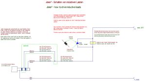
Connect the inductive load, as shown in the circuit diagram (klick for download), to a 2.5 mm stereo jack plug. The power supply may be a power adaptor with the required output voltage and power (in the circuit diagram the two poles are depicted as +U and -U).
Important note: The flyback diode is mandatory! If it is missing, voltage spikes of several hundreds of volts may destroy the output while switching off the load! Pay attention to the polarity of the diode.
For loads heavier than 300 mA (continuous) or 500 mA for less than one second two switches may be tied parallel. Therefore see the optional branch, marked green.

